Motor-CAD
Motor-CAD is a unique software package for the electromagnetic and thermal analysis of electric motors and generators.
It is used by many leading motor manufacturers and universities world wide to optimise the cooling of a wide variety of motor types and cooling methods.
The software is used to provide rapid analysis of design and manufacturing changes. Its analytical based algorithms give instantaneous calculation speeds and allow ‘what-if’ analysis in real time. The fast calculation speeds are a real plus for modelling of complex duty cycles such as traction motor drive cycles and application such as elevator load cycles.
The software has a highly developed user interface that makes for easy data input and interpretation of results.
- brushless permanent magnet motors (BPM),
- outer rotor BPM motors,
- induction motors,
- permanent magnet dc machines,
- switched reluctance motors,
- synchronous machines,
- claw pole machines,
- universal motor.
Motor-CAD electromagnetics modules are available for the following motor types:
- brushless permanent magnet motors (BPM),
- induction motors.
Motor-CAD thermal models are available for the following cooling methods:
- natural convection (TENV),
- forced convection (TEFC),
- through ventilation,
- water jackets (several configurations),
- submersible,
- wet rotor and wet stator,
- spray cooling,
- radiation,
- conduction.
Additionally the user may include in the model various mounting configurations that can heat up or provide extra cooling to the machine.
The thermal model in Motor-CAD is based upon analytical lumped-circuit analysis making it extremely fast to calculate. This allows the user to perform ‘what-if’ calculations in real time.
All the thermal resistances and capacitances in the Motor-CAD model are calculated automatically from geometric dimensions and material properties. The user need not be familiar with complex heat transfer phenomena such as dimensionless analysis of convection.
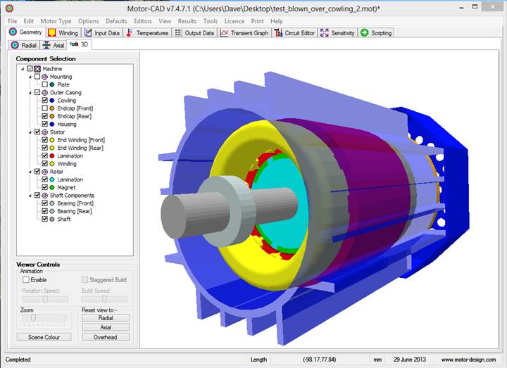
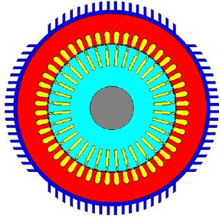
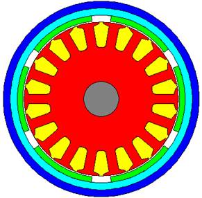
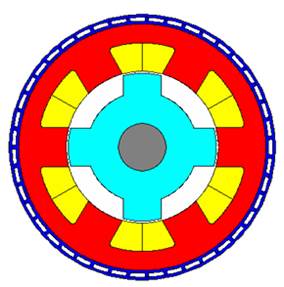
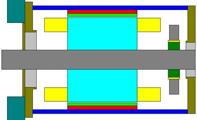
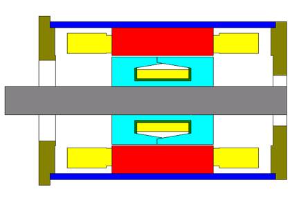
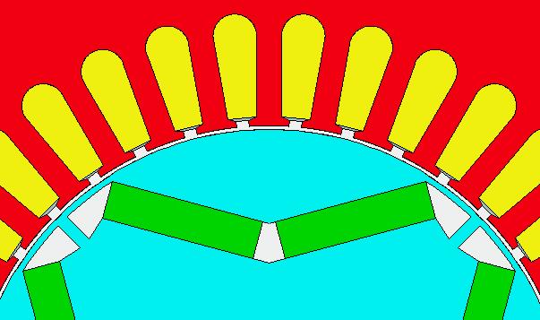
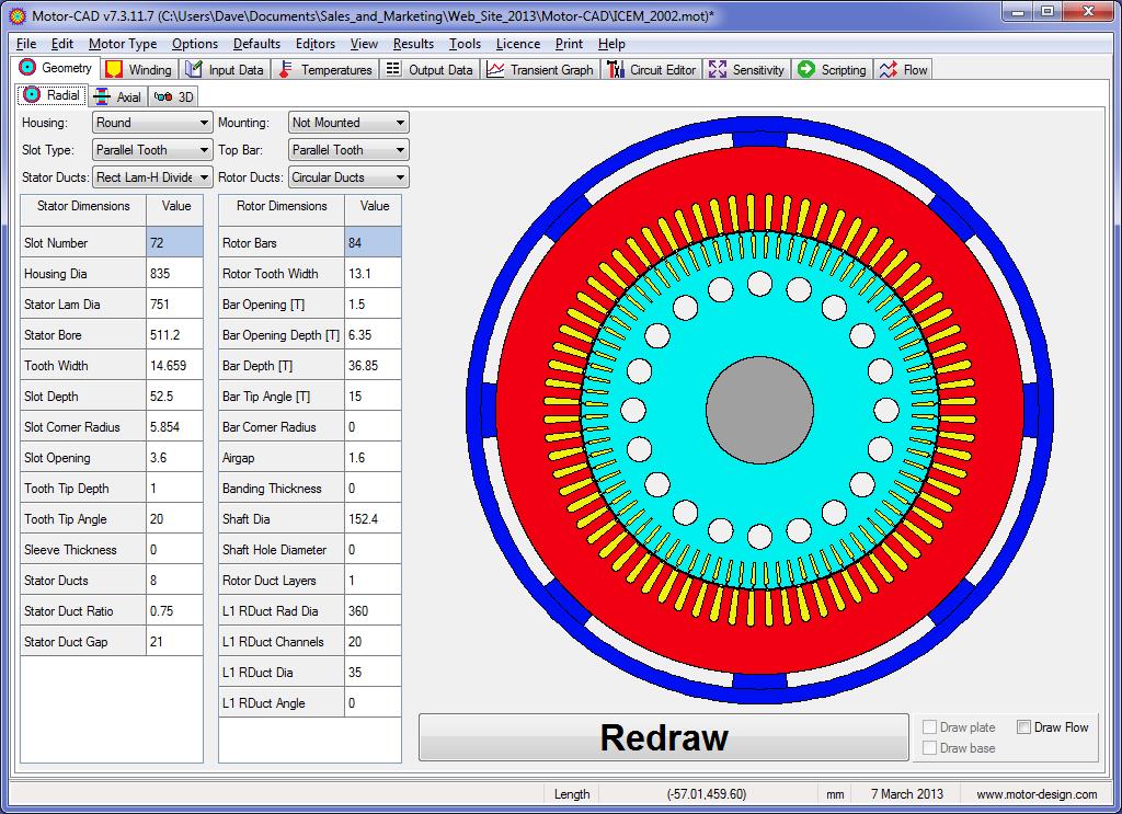
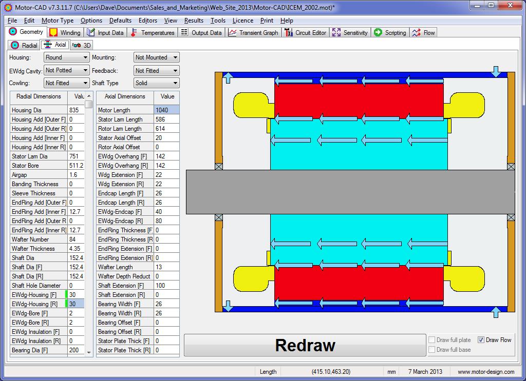
The cross section of the motor to be analysed is input using the graphical editors shown below:
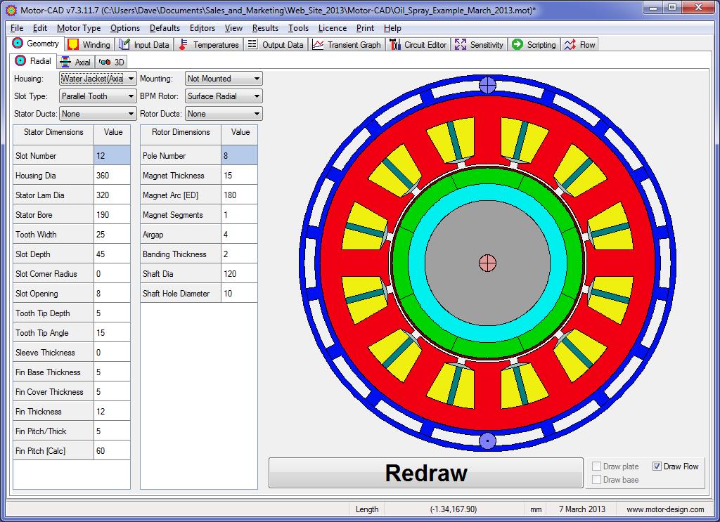
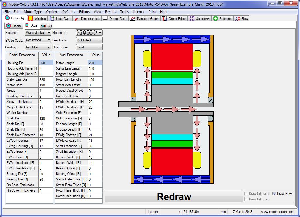
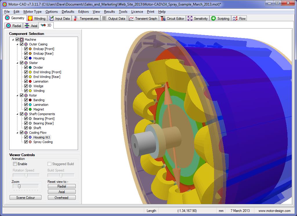
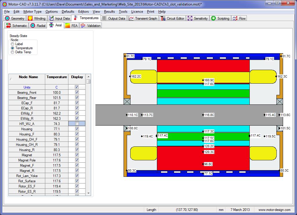
Both radial and axial cross-section editors are required such that the 3-dimensional aspects of heat transfer can be modeled. The visual feedback provided is useful for eliminating errors in data input and gives the user an indication of the main heat transfer paths.
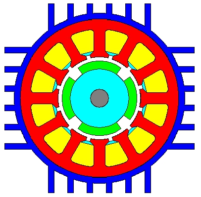
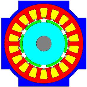
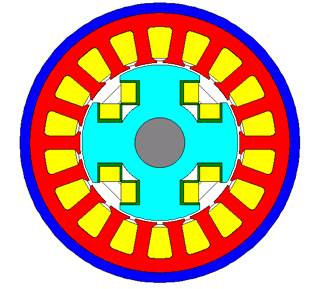
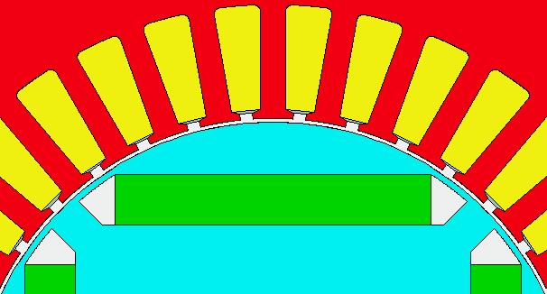
Many geometry options are available. But also have things like brushless permanent magnet shape, induction motor bar shape, stator and rotor ducts shape, etc. A few of the many examples shown below:
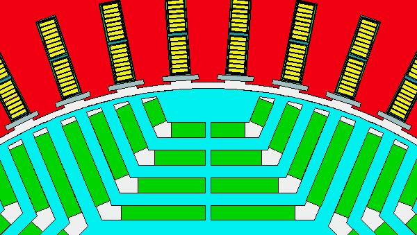
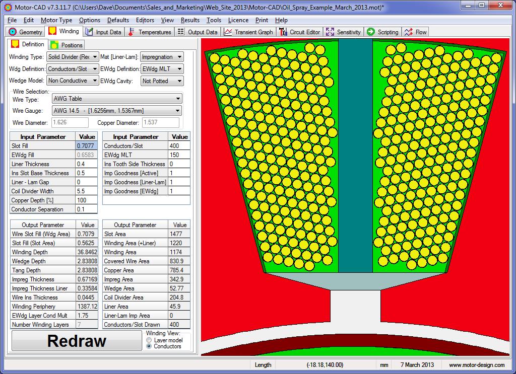
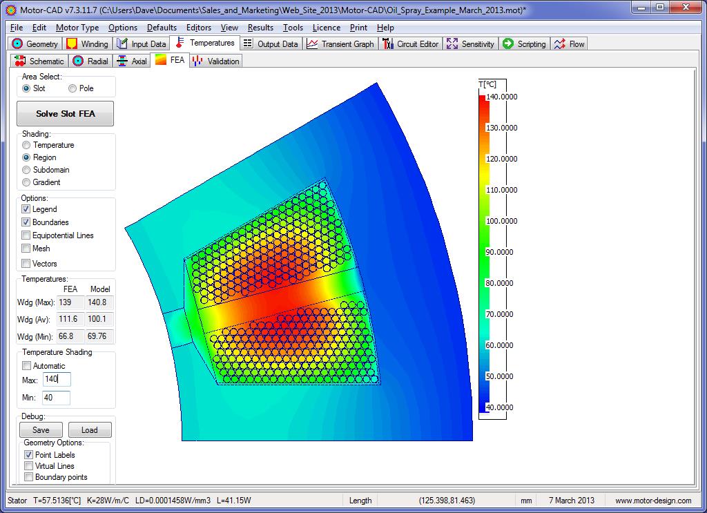
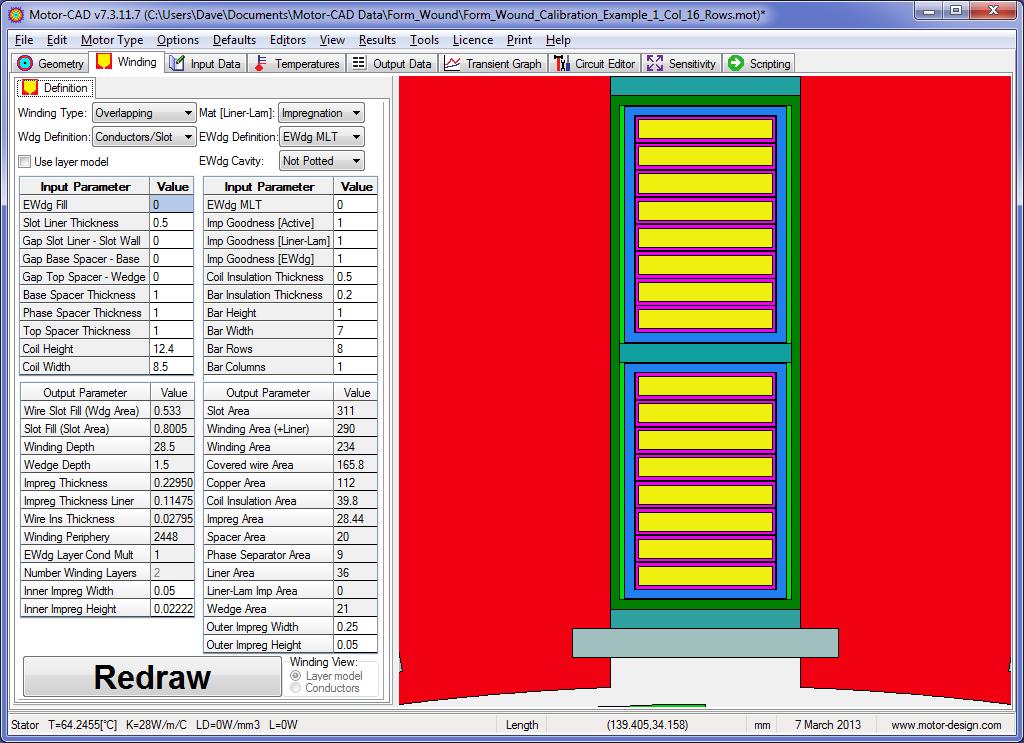
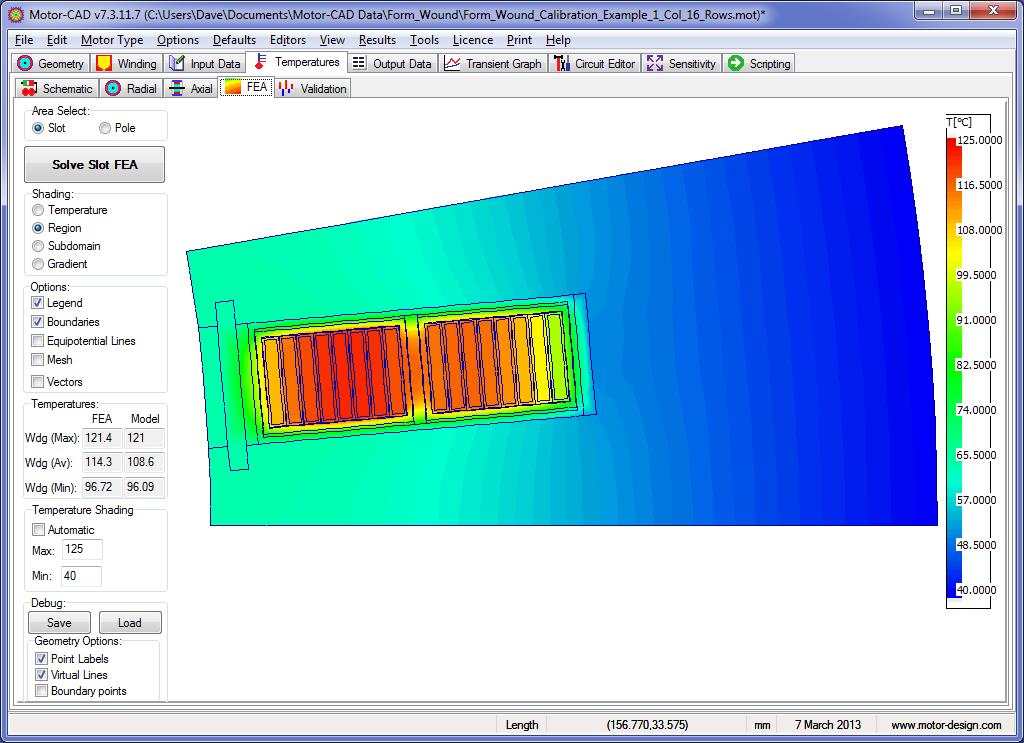
Motor-CAD can accurately model the heat transfer through stranded random or precision wound windings and form wound winding. The intricate insulations systems used in the slots can be modelled. The fast analytical model for winding heat transfer has proven very accurate allows fast steady-state and thermal transients to be calculated.
Examples of the conductor placement editors and the integrated FEA are shown below.
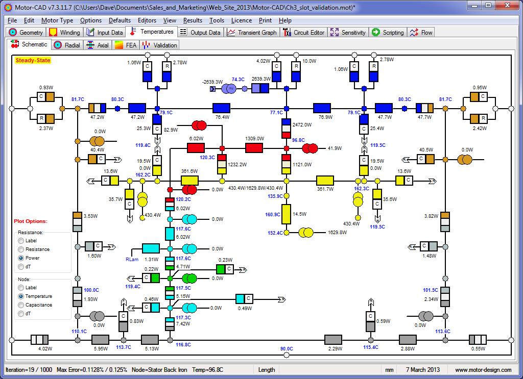
Below we see a screen-capture of the schematic diagram solved. This diagram is used extensively for post processing of steady-state calculations. The resistances and power sources shown in the schematic are colour coded to the components shown in cross-section editors. Resistances with a vertical orientation represent radial heat transfer and those with a horizontal orientation represent axial heat transfer. Those with a ‘C’ in them are convection resistances and those with an ‘R’ are radiation resistances. Resistances plotted in two colours represent interface resistances between two components.
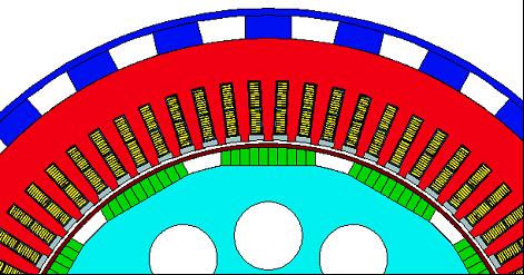
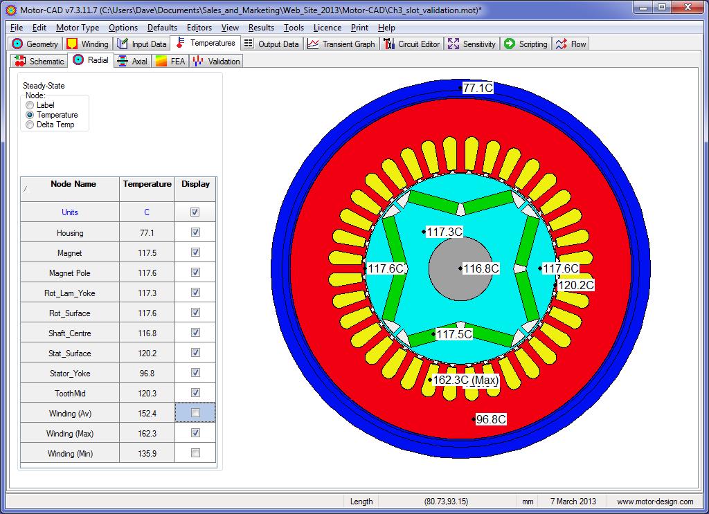
The temperature data can also be overlayed on the motor cross-section:
For cooling types such as through ventilation the fluid flow must be predicted before the heat transfer circuit can be calculated. Flow network analysis is used in Motor-CAD to calculate the flow of fluid through the machine. Often in a through ventilated machine this involves flow in three parallel paths, i.e. stator ducting, rotor ducting and airgap. A typical flow circuit calculated in Motor-CAD is shown below:
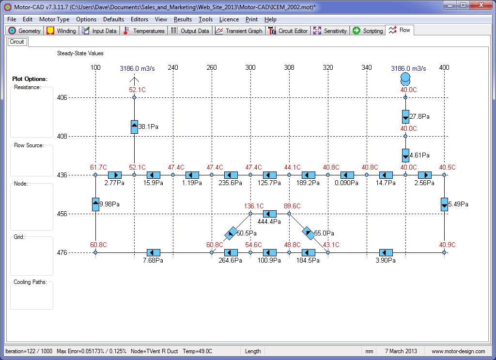
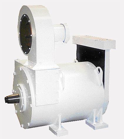
The above flow path is for the through ventilated induction motor sown below:
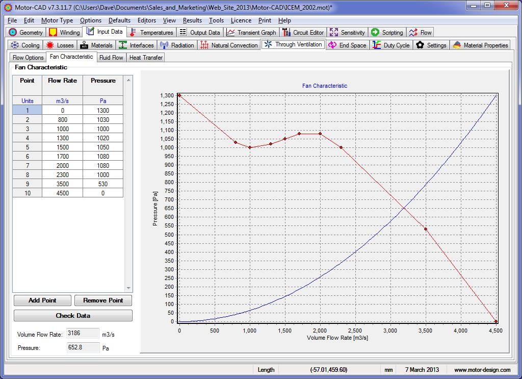
The user can input the characteristic for the fan. The intersection with the calculated system resistance characteristic is used to determine the total flow through the machine – see below:
Thermal transients can also be modeled, in which case thermal capacitances are automatically added to the circuit. It is essential to carry out detailed thermal transient analysis when using complex duty-cycle loads if the motor is to be driven to its full potential. The graph below shows a typical thermal transient.
![]()